Friday, December 27, 2013

Safety Fast


The title of today's post - "Safety Fast!" - comes from Triumph's arch-rival in the British sportscar world, MG.  I've always thought it was a pretty clever slogan.  Performance means safety, they're saying, and they're right.  It's a philosophy that SAAB used to counter Volvo's "Swedish tank" reputation back in the 1980's: the safest accident to be in is the one that never happens, because you had the visibility, agility, power and/or braking to avoid it.

To that end, today's work session focused on a couple of safety-critical systems: brakes and steering.

Tie Rod Ends

The tie rods connect the steering rack to the front wheel assemblies.  The rack slides sideways as the steering wheel is turned; the tie rods translate that horizontal motion into steering motion by push-pulling the hub assemblies, which pivot on the vertical axis, so that the wheels point in your new, desired direction.

The steering rack assembly is mounted firmly to the chassis, while the wheels need to be able to travel up and down on the suspension, so the tie rods incorporate a ball-and-socket joint at either end to permit that movement.    The joints on the outer end of the tie rods are removable, because they tend to get worn and damaged by road debris, heat from the nearby braking surfaces, and the stresses put on them by the steering forces.  Besides, threading the tie rod ends along the tie rods provides the adjustment needed to perform front end alignment.

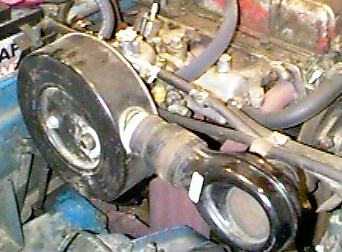
This old tie rod end was an accident waiting to happen.
Scary!
The tie rod end is protected by a rubber boot to keep the moving parts clean and greasy, the way they ought to be.  Once a tie rod end's boot fails, the surfaces are subject to grit, water, and gradual loss of grease.  Eventually, the cup that keeps the ball from popping out of the socket fails.  When this happens, you'll suddenly lose steering control on that side just after hitting a bump; the two front wheels will point in different directions, and the car will probably end up going straight into whatever is directly ahead,  possibly shedding parts as it does so.

Personally, I hope never to find out what it's like to be in a car when that's happening.  So when I inspected the tie rod ends and found one boot entirely missing, with damage visible to the ball and socket beneath, I figured now was a great time to pop in some new ones.

Luckily, the P.O. had provided spare tie rod ends, as well as spare boots to protect the inner ends of the tie rods.  

New boot and tie rod end in place.
It's a simple enough job.  The tie rod ends themselves are sort of press fit into the tie rod levers on the hubs.  Removing them requires a "pickle fork" - the clever colloquial name for the tie rod end remover.  But I have one of those, and was able to free things up pretty easily.  

Once the old tie rod ends are removed, you can slide the old boots off, slide the new boots on, thread on the replacement tie rod end, and tighten everything down.  You may need to perform an alignment, but that's the extent of the tricky stuff.

Well, except for the fact that the boots are tight, and end up all greasy when you're trying to put them on.  I couldn't for the life of me figure out how to get the things seated.  Vic from the Triumph Experience forum to the rescue: soak the end of the boot in boiling water for a few minutes, so that it will be pliable.  Then you'll be able to stretch it into place better.  I found that, even with the boiling water trick, it took 6 or 8 tries to get it.  But get it I did, eventually.

Then it was a simple matter of getting the new tie rod ends installed.  I showed my boys how to use a torque wrench while we were at it.  

The alignment will wait until we're closer to getting this thing on the road.  But hey, don't let me forget it, okay? 


Front Brakes

Both brake calipers will get wire brushed clean,
overhauled, and painted with caliper paint.  
When the P.O. sold me the car, he described it as "needing rear brakes."  I took this to mean that the front brakes were fine.  But the fact is, they look pretty rough.  The pads looked okay, but the rubber brake hoses are cracked and aged, and the steel brake pipes are rusty.  The disc calipers look weathered, but there were no obvious signs of fluid leaks.

I'm sure there are cars on the road in similar condition, but it would be criminal not to fix the rusty and cracked hydraulic lines while I've got the brake master cylinder out. Luckily, the P.O. provided an expensive set of copper brake pipes with the car.

The brake discs don't show much wear, so I
should be able to just get them machined smooth and reinstall them.
So I disconnected the hoses and took a crack at getting the hard lines free, too.  That might take some doing, as the hard lines are corroded and pretty stuck in their T fittings.  For now, I soaked 'em in WD-40 and let it start to penetrate. 

I'll gradually remove the rusty hard lines and install their shiny copper replacements as I'm able to break things loose.   Meanwhile,  I pulled the calipers off, so while I'm waiting for the WD-40 to do its job, I can clean, overhaul, and paint the calipers.  

And I'll try to get the rotors machined, if they are within specification, or replace them if they are not.  And while I'm doing that I might as well replace the front wheel bearings. And....

That "While I'm at it" phrase is a dangerous one, because "while I'm at it" I might as well strip everything down to bare metal, weld in new rocker panels and floors, and overhaul the engine.  We're trying not to end up there.  But brakes and tie rod ends seem like a no-brainer: I don't want to get this thing running only to run it into a bridge abutment when some critical safety system fails.

Wednesday, December 18, 2013

Rear Window

Last week, the long-anticipated used rear window for my hard top showed up in the mail.  It survived the trip, and was in good shape, though a little dirty.  I cleaned it up and made ready to install it.  I had already received the rubber gasket that surrounds the window, so nothing was holding me back from putting the window in.

To Paint or Not To Paint?


Nothing, that is, except the feeling that maybe I ought to get the hard top repainted while I had the window out.  It's got a spot in the center of the leading edge where the paint has flaked off, exposing bare metal beneath.  I decided to call a few body shops and find out what it would cost to get the top painted.

It turns out that a professional repaint of the hard top would cost around $400-600.  As much as I'd like to do it, that's just not in the budget right now.  I'll have to handle the paint trouble with touch-up paint.  So, armed with that decision, some slave labor from the kids, and a nice warm day to do the work, I went out yesterday to get the window installed.

Installation: The String Method

I've never done anything like this.  I've never even read a how-to about it online.  But I did hear one reference to "the string method" for installing windows, in which the guy mentioned pulling on some piece of string from the inside while his friend pushed on the window from the outside.  That was enough to figure out what to do.
Pull the rope to the right, past the gasket flange
in the hard top, and the gasket will seat correctly.

The gasket had two slots in it.  The one intended for the glass was really deep; the other was intended for the flange in the hard top, and it was significantly shallower.  So I installed the gasket on the window, and got a piece of 1/4" nylon cord that I pressed into the other slot in the gasket, all the way around.  There were two tails left over, sticking out of the gasket in the lower corner.  Out we went to the car.

I'm pulling the string while Calvin...
persuades the gasket to cooperate.
I put the two free ends of the cord into the car, set the window in place, and instructed my biggest, strongest kid to press hard on the gasket right there at that point.  I then pulled on the cord, which peeled the lip of the gasket over the flange as the cord pulled free of the gasket.  Calvin moved his hands to provide pressure at the point where the cord was peeling free from the gasket, and around we went.

There were a couple points where the gasket was really reluctant to cooperate, and I was pulling hard enough I was worried I'd break the skin on my hands.  We took a break, lubed the recalcitrant parts of the gasket with some silicone spray, and I improvised a pulling handle out of a crescent wrench.  Work continued.... and suddenly we were done.  Elapsed time was probably less than 20 minutes.

Ta-da!
The only thing left to do was to press in the decorative silver bead that surrounds the window.  That went even more smoothly, and, for only $275 and 30 minutes of (DIY) labor, the hard top is weather-tight.  It looks pretty darned good, if you ask me.  And now I know how to do it.

Oh, and one more thing:

Never Put Duct Tape On A Car's Finish

When we had a big, windy snow storm bearing down on us, I made the decision to duct tape sheet plastic and plywood over the opening to protect the Spitfire's interior from the weather.  As I did it, I wrote:
When the window arrives, we'll pull this wart off and see what violence the duct tape does to the paint.... 
How prescient.  The duct tape pulled off a couple of large (thumbprint-sized) patches of body paint, and another strip pulled a few smaller spots off.  Once I'm able to get some #82 Carmine Red spray paint, I'll need to do some spot repairs on the paint damage.

Oh, well, it's not as if I could have left the tarp on.  The flapping in the wind caused some paint damage to the driver's side door, too.  Maybe I need two cans of #82 Carmine Red....


Friday, December 13, 2013

What Have We Here? (Cont'd.)


One thing that's been confusing me lately is whether I have a Mk. IV or the next model, the "Spitfire 1500," which was introduced in 1975. One notable difference is the engine displacement: the Mk. IV continued the 1296cc engine from the Mk. III, while the 1500 had, you guessed it, a 1493cc engine. (Close enough.) My 1974 Spit says "Spitfire IV" on the badges, so it's the 1296cc mill, right?

Well, not so fast. A lot of very experienced Spitfire owners on the forums I now frequent talk of their "1973 Spitfire 1500," for example. How could they have a 1973 1500 when it wasn't introduced until 1975? Something didn't add up.

Tonight, I found some clues while looking for carburetor resources. Spitfire & GT6 Magazine has a page devoted to clearing up model year information, and right there in black and white, it says:

There is some confusion about what is a Mk4 and what is a 1500. All 1971 & 1972 cars were MkIV's.US 1973 & 74 cars (FM commission numbers) received the 1500cc engine (to try to counteract the strangulating emissions regs in the US) while the rest of the world stayed Mk4's with 1296cc engine. These cars were essentially MkIV's with 1500 badges and engine.

So what *do* I have?

My car carries commission number FM14102U*. The "FM" indicates it was a US model; the "14102" places its date of manufacture squarely in 1974, which jives with the March 1974 date on the VIN plate; and the "U" at the end indicates that it was equipped with "Federal" (that is, US government and not the stricter Californian) emissions equipment.

* "Commission Numbers" were the equivalent of VIN's (Vehicle Identification Numbers) used on pre-1979 cars. There are reasons that a commission number is not a VIN, but they are only interesting to insurance companies and government DMV offices. For our purposes, it's the same thing.
By the way, paint code #82 is "Carmine Red" - a deep red that looks exactly like what my car wears. This answers a couple questions, as well, because the bonnet shows signs of having been painted that color atop an earlier yellow coat. Was the car originally yellow? No, the paint code indicates the bonnet is off a different car, probably due to front-end accident damage. But the good news is that I can easily buy #82 paint in spray cans and touch up any areas I need to, like the bulkhead I recently primed in flat black.

Anyway.... FM14102U means I have the 1500 engine, right? Well, not so fast. According to the excerpt above, it should be badged as a 1500 if it has the 1500 engine. I've seen pictures of a 1973 Spitfire 1500's badges. Mine doesn't have them - it's badged as a Mk. IV. And besides, it's anyone's guess whether this is the original engine.

The only real way to tell what I have is to look at the engine number. I poked my head under the hood and found this:


Deciphering FM56740UE

"FM" means the 1493cc "1500" engine, and, again, the "UE" designates a US-market engine with the Federal emissions controls. So I have a 1.5L car. Bigger is better, right? Maybe.... The two engines are substantially the same - the difference is primarily in the crankshaft, which is modified to increase piston travel ("stroke"), and built more heavily in the 1500. This increased travel means that the piston must move farther, and is subjected to higher G-forces when it reverses direction, at the same RPM, than in the 1296cc. Coupled with the higher mass of the 1500 crankshaft, higher G's multiplied by more mass means that the 1500 is under significantly more stress, and thus more prone to high-RPM failures. Track racers strongly prefer the oversquare 1296cc engine for this reason, because high-performance track driving is much more often done in the vicinity of max RPM. You can read a detailed discussion of these issues here on the Triumph Experience Spitfire forum

But street driving is typically done between 2000 and 4000 RPM (2000-3000 for cars driven conservatively). And the longer stroke provides increased low-RPM torque, which translates to quicker acceleration from stoplights and such. The Spitfire 1500 was actually faster from 0-60 than the earlier cars, even though it was less successful (and less durable) on the track. The slightly overstroked 1500 engine should be fine for a lot of what I intend to do with the car.

It may not be fine for all of what I want to do with the car, though. The 1500 produced around 50 horsepower, compared to over 70 for the smaller Mk. III engine. That difference is likely to be apparent on long hills at highway speed, or, well, everything else done at highway speed. The Spitfire 1500's top speed is around 85mph, which is about the average pace on I-25 between Fort Collins and Denver most weekends. Highway driving will probably be a terrifying ordeal, with my poor little engine spinning desperately fast to stay out from under the hungry SUV's all around it. Maybe I'll take the back roads....

High Compression Model

But wait! The "56740" portion of the engine number implies that the engine is not original: this reference page puts the engine in the 1976 model year. The 1976 Spitfires were unique in the USA because they had a higher-compression head installed, running at 9:1 instead of the 7.5:1 compression of earlier and later US-model Spitfire 1500's.

I've always thought higher compression ratios were better, but I've never really understood why. So I looked it up on Wikipedia:

A high compression ratio is desirable because it allows an engine to extract more mechanical energy from a given mass of air-fuel mixture due to its higher thermal efficiency. This occurs because internal combustion engines are heat engines, and higher efficiency is created because higher compression ratios permit the same combustion temperature to be reached with less fuel, while giving a longer expansion cycle, creating more mechanical power output and lowering the exhaust temperature.

Non-US 1500 models with the 9:1 compression ratio and twin SU carburetors produced almost 20 horsepower more than their emission-control-choked and compression-tamed US brethren, and were capable of 100 mph top speeds. Now there's a thought....

Normally, an engine swap could mean a lot of things. It might simply mean that a previous owner blew an engine and pulled any old replacement out of a junkyard to get his car back on the road. But the 1976 engine number makes that unlikely. The 76's were rare and valuable enough that you probably didn't accidentally end up with one. This was probably an engine swap done as an expensive performance upgrade.

Whadya know? Apparently my car used to be somebody's baby.


Some Uncertainty Remains

Of course, it's possible that my fancy high-compression engine suffered a head failure at some point, and had a lower-compression non-1976 head installed. There's no sign that this has happened, but it can't be ruled out. I'd like to find out if there's a way to determine, empirically, whether the engine is indeed the high-compression model.

Anyway, that's what I have to work with. I'm inclined to minimize alterations to the car until after I've had the chance to drive it a bit. If it turns out to be sluggish and I plan to keep it for the long haul, I might look into a twin carburetor conversion, exhaust headers, electric cooling fan & fuel pump, electronic ignition.... Whoops, I just daydreamed $2000 of improvements for an $825 car. Easy, there, tiger.


Thursday, December 12, 2013

Carburetor Rebuild, Part 1

With the alternator reassembled, the next item on the to-do list is the carburetor.  The Previous Owner (PO) indicated that the carb would need "adjustment or rebuild".  Vague....

Well, it turns out that carburetor rebuild kits are only about $35-40, and I like the idea of going through it completely, rather than wrestling with a carb in unknown condition.  Besides, it's mid-winter.  A carburetor rebuild can be done indoors, with time that would otherwise not be available to work on the car.

So, where to start?  Well, first of all, what do I even have?  The carb is stamped with markings identifying it as a Zenith Stromberg.  A little searching online turned up this image and accompanying text:
The Zenith Stromberg CD150 series fitted as stock to later North American market Spitfires. Not the best "performance" choice. Many of the subassemblies are not adjustable or rebuildable. Lots of attached hoses and fittings. Early ZS carbs were manual choke. Later ones used a water heated auto-choke. Also shown here is the giant air filter / thermostatic air control contrivance.  [Photo and text courtesy Bob Sykes, taken from his brief writeup on Spitfire carburetors on VTR.org]
Yup, that's my carb, and that's definitely the unmistakeable "giant air filter / thermostatic air control contrivance" sitting in my trunk.  So I have the stock, but suboptimal, carb option on my car.  Not a huge surprise.  I was gratified to find that at least my Zenith has the earlier manual choke, rather than the much-maligned automatic thermal choke system. 

Should I replace it with one of the other carburetor options, say, twin SU carbs from an earlier Spitfire, or a Weber model?  Nah, those upgrades cost many hundreds, even thousands, of dollars.  Let's just get it running and see what we have, shall we?

With that in mind, I did a little looking around for instructions, parts, and so on for the Zenith Stromberg CD150 carburetor.  Here are some resources I found.
I pulled the carburetor off of the manifold during a "warm" 25-degree afternoon.  It's currently sitting inside, awaiting the rebuild kit and a little free time.  Stay tuned!


Saturday, December 7, 2013

Alternator Reassembly

I got the alternator mostly reassembled today.  With temps still in the single-digits or teens (Fahrenheit), it was nice to have an indoor project.

I had intended to replace the drive-side bearing, but I couldn't press the rotor free of its housing to replace the bearing, so I left well enough alone.  I'll be satisfied to replace the rectifier (a.k.a. diode pack), voltage regulator, and brushes.  Here's the entire top of the reassembled alternator, with the new voltage regulator on the left, the new brushes on top of the slip ring cover in the center, and the rectifier at right.
Everything went back into the alternator in pretty obvious ways.  I didn't even need to consult my photos of the alternator taken during disassembly.  (The one exception was making sure I got the wire connections right on the slip ring cover, for which I drew myself a picture.)  Everything else fit together like a puzzle.  Even the stator leads engage the rectifier diode leads in obvious ways.
Rectifier installation involves soldering the leads from the three stator coils onto the diode leads on the rectifier.  Certainly the trickiest and most skilled step of the whole process - but just a couple of fairly large solder joints, after all.  I am not particularly skilled with a soldering iron, but I'm capable of this, at least.
And like that, the alternator is (theoretically) reassembled.  I'll wire-brush and paint the alternator fan and pulley before reassembling everything, because they're a bit rough-looking.  And then we'll hook everything together and see if the smoke stays in the darned thing this time.  I have high hopes....

Tuesday, December 3, 2013

Mounting Brackets Again


The brackets I primed yesterday were calling out to get their final silver coat today.  Here they are, in all their shiny glory.  After our weather moves through, I'll install these on the freshly primed bulkhead, and we'll be ready to start putting things back together.


Monday, December 2, 2013

Mounting Brackets

Cleaned & rust-converted example at bottom,
primed pieces above
With weather on the way, I've turned to projects that can be done indoors.  The alternator is a prime candidate, but I'm still waiting for the brushes to get here. 

That leaves rust mitigation.  At the beginning of the bulkhead job, I pulled a bunch of brackets out of the way.  They were fittings for the master cylinders, speedometer cable, ignition coil, etc.  Each had its own sad patina of rust, grime, and road dust.  So I went over them with the wire wheel while the weather was still good enough to do it outside.

Once they'd all been brushed clean, I wiped them all down with a rust converter and set them aside for 24 hours.  A day later, I came back and primed them.  Tomorrow, I'll hit them with a coat of metallic silver Rustoleum and they'll be as good as new - or, rather, as good as I'm likely to get them, which is more than adequate.

A quick word about my indoor paint setup.  I sealed up the edges and corners of a cardboard box, shoved a wire hook through the side of it pretty deep within, et voila! Indoor paint booth.  Overspray is contained.  The fumes still require an exhaust fan or an open window, but it's manageable.

The wire hook - a bicycle spoke, in this case - is bent to form a handle so that the work can be rotated in the booth to hit it from all sides.  Works pretty smoothly!

Detail of the handle for rotating the work
in the paint "booth"

Winter is coming....

An earlier storm provided just a couple inches.  Closing the tarp in the doors
keeps it attached to the car so it covers the missing rear window.
But this next storm isn't kidding around; the tarp has to go.
Word on the street is that an honest-to-goodness named winter storm is bearing down on us.   In a day or two, we expect 6-10" of snow and daily high temperatures around 10 Fahrenheit.  Our salad days of November shirtsleeve driveway sessions are coming to an end.

The storm's harbinger has been 50+mph wind, which set the tarp on my poor Spitfire flapping more than I could bear to watch. And our steel roof tends to dump piles of snow onto the driveway right about where the Spit sits, so a tarp probably isn't going to cut it any longer.  

I'm still waiting for the replacement window I sourced via a fellow forum user at The Triumph Experience.  Sure would have been nice to get that glass installed before the storm hit, but that's not in the cards.  So I looked for a plan B.  

The best idea I could come up with on short notice was a piece of scrap plywood cut to sit a little outside the window opening, taped in place with duct tape and sheet plastic.  It should be weather-tight, and solid enough to withstand the snow we're expecting.  It's ugly, but not as ugly as having the back half of the car covered in a faded, flapping poly tarp.  At least now I can see the car's lines.

When the window arrives, we'll pull this wart off and see what violence the duct tape does to the paint....